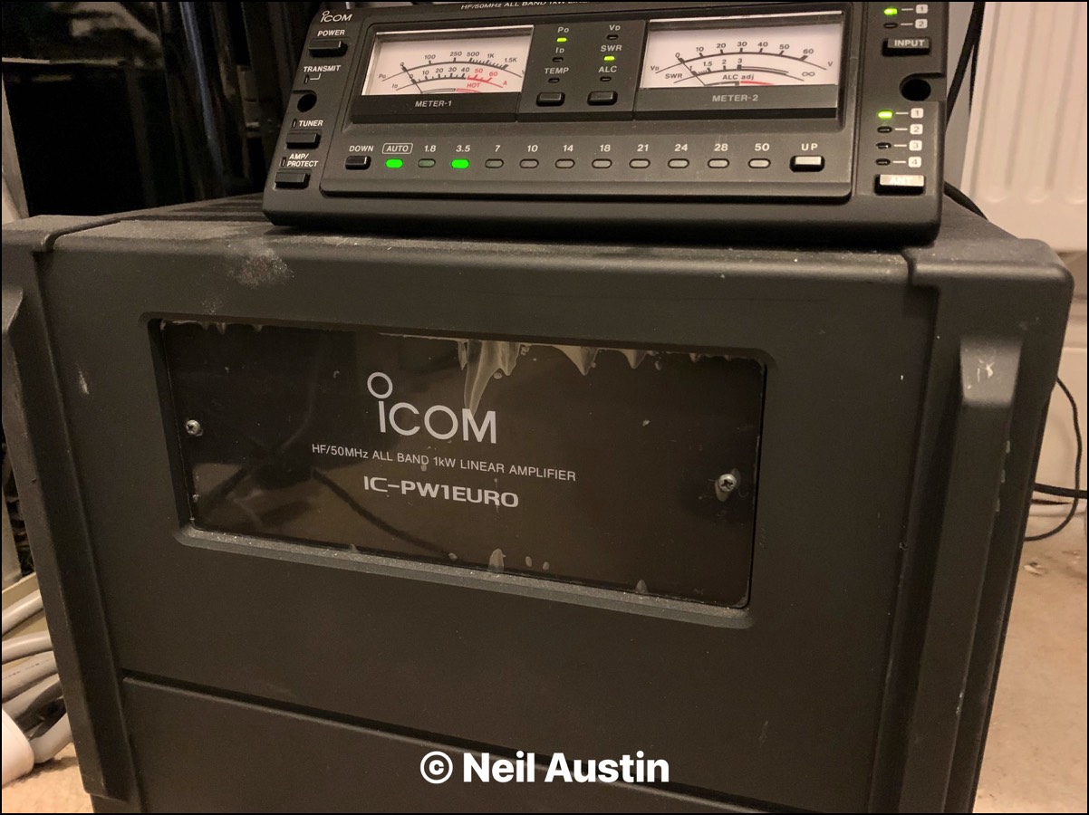

<i>Icom</i> <i>IC-PW1 Euro</i>
  • © 2026 Neil Austin Contact Me 0

Icom IC-PW1 Euro

Stacks Image 3

Station Deployment: The Icom IC-PW1EURO 1kW Linear Amplifier

I have integrated the Icom IC-PW1EURO into my shack to serve as the heavy-duty power infrastructure for HF and 6-metre bands. While it is a highly automatic and stable 1,000-watt deck, it demands exact installation parameters to avoid damaging the internal power amplifier (PA) boards.


Hardware Bench Profile & Station Integration
Parameter Profile My Operational Specification
RF Power Output 1,000 Watts (1 kW) continuous PEP output (1.8 MHz – 50 MHz)
Integrated Tuning Heavy-duty high-speed automatic antenna tuner (Auto ATU)
Control Topology Multi-transceiver tracking via bidirectional CAT CI-V bus routing
Physical Footprint 25 kg (55 lb) combined chassis with a detachable remote control head
Power Infrastructure Direct 230V AC high-current line (configured for European tracking)
Critical Caveats & Protection Configuration (RTFM Checklist)

Before keying a full kilowatt out of your shack, several vital protection mechanisms and hardware parameters must be strictly aligned to prevent hardware failure:

  • Exciter Drive Limitations: The PW1 accepts dual transceiver inputs via INPUT1 and INPUT2. The maximum drive limit from your exciter must never exceed 100 Watts. Driving the input stage beyond this threshold risks immediate attenuation or damage to the input sensing lines.
  • ALC Voltage Alignment: Properly adjusting the ALC potentiometer lines using a steady CW/RTTY reference tone is mandatory. This acts as your physical software-hardware failsafe to ensure your transceiver automatically backs down its drive levels during peak loads.
  • SWR Threshold Faults: The internal CPU actively monitors your antenna system's Standing Wave Ratio (SWR). If the tuning grid shifts outside of the matching boundaries, the amplifier will instantly trip its protection circuitry to protect the expensive output transistors from excessive reverse voltage.

Custom Hardware Modifications: The CAT CI-V Control Bus
The factory configuration of the PW1's control line arrangement has some inherent limitations regarding data collision when mixing multiple third-party software rigs.
  • The Mod: I have modified the internal CAT CI-V control bus routing.
  • The Result: This modification isolates the data streams, ensuring clean, bi-directional frequency tracking across my Icom rigs and the SDRplay panadapter layout without causing timing lag or command dropouts.

I've had this Linear amplifier for a while now. Although it has it's caveats which can lead to creating issues (damaging) the amplifier itself, providing you take care in its set-up (RTFM), I have had great performance from this heavy and large amplifier.
There are some mods you can do mainly to do with the CAT CI-V control bus. The problem is, when HRD is connected to the IC-9100 under some conditions, the PW1 can Switch band and back again out of the blue whilst transmitting.
I believe this is still a problem on mine. I will in time investigate as soon as I get the chance but if I use a different control interface, like 'Flrig' etc. I don't seem to get the issue. I believe, it is also something due to the logging program on HRD in conjunction with HRD. If I use HRD log on its own with 'Flrig' I don't get an issue. We'll see.