Still learning, one day at a time...
<i>G6DSG</i>  <i>Welcome</i>
Information Web Server
  • © 2019 Neil Austin Contact Me 0

G6DSG Welcome

Icom IC-9100 Hf, VHF UHF Multimode Tranciever (DStar)

Stacks Image 3
About the Icom IC-9100
This model of transceiver first made its appearance in 2011.
As a licensed Radio Amateur, I can use this transceiver to transmit and receive on the designated frequency bands stipulated within my licence.
Ive been licensed since I was about 19 years of age being influenced by the CB era at the time.
It covers bands and you can select many modes to operate under such as CW (morse code), RTTY, Sideband modes LSB USB.
You can choose a link opposite to discover about the various modes and what they do but there are however, more modes of operation not covered in the links but I will endeavour to expand the site and describe them later.

Modes of operation

As I have already mentioned, with the IC-9100 you can chose many modes of operation. Here are some links to Wikipeadia for a general and technical insite into the various modes of operation.

  • CW Morse Code
  • RTTY Radio Teletype
  • AM Amplitude Modulation
  • FM Frequency Modulation
  • LSB Lower Side Band
  • USB Upper Sideband
  • DV Digital Mode of operation used by ICOM commonly known as D-Star.

Updating the IC-9100

Iv'e had the radio a while now and it has served me and others very well. As time goes by, other innovations come along in radio which cause some to move on to other up to date models because they are better or have quirks which can make the use of the radio easier or better.
One of the innovations that have come about because of SDR (Software Defined Radio) is that of a waterfall display of the particular band or spectrum you may be on. Also whilst 'working' that band, you may see a signal in the spectrum of the display of interest and these days, using a mouse connected to the Radio and a large display, click on that signal and immediately go to that frequency. This means the rig magically retunes itself and you can listen and work that station. Also, by looking at the pattern of the waterfall display, you can very often determine the mode of operation ie. RTTY, Morse PSK etc.
Without getting into a big debate, I don't particularly want to update to SDR so it got me thinking, could I modify the 9100 with a panadapter output so I can connect an SDR receiver and control the radio like the new ones do? After researching on the internet it seems you can and one or two others, to varying degrees, have done just that. Now initially, at this stage it looked all quite straight forwards but as I delved deeper, it seems there were some caveats to overcome first.

Choosing the Panadapter for the job

Stacks Image 34
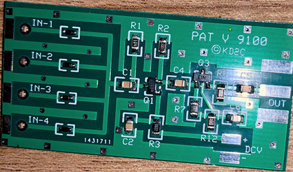
This is a 4 channel High Z Pat board from …… His site had single channel PAT boards for various Radios but on further study, this one was specified for the IC-9100. It is supplied with an optional connection kit and instructions on the various connection points to connect to. Great I thought, except on further reading elsewhere I found articles which said after the successful install and connection to an SDR receiver, the S meter readings were low when selecting the bands and also at VHF, UHF & 23cm, it had possibly made the receiver in the radio a little deaf.
What we need to do therefore, is to make sure the impedance of the connection point and capacitance from the coax doesn't alter or have an adverse effect on the signal when the board is hooked up.
A solution, which was tried by the Brisbane VHF Group, was to modify the 23cm unit of another model of radio. This worked by putting a LNA into the path and split the tapping point. Connect this to the Hi Z input of an LNA and by then modifying the LNA o/p, bringing its gain back down whilst in series with the tapping paths by using a Pi attenuator. Another tap can then taken from the o/p of the LNA just before the Pi attenuator which we can then send to the PAT with at least 24dB of gain. This may sound confusing, but here is the circuit of what I mean. I chose a similar LNA to another article I read and computed the values of the Pi attenuator to give me unity or very little gain. Having that little more gain can only help the rigs receive and its 0.6dB noise figure would have to suffice. I could also do the same for the VHF and UHF side too. Let's give it a punt!
Stacks Image 36
Stacks Image 38
Before we do anything, I will check if this amplifier is working and its gain over a specific frequency response. This will mean checking at both outputs and to see if the Pi attenuator does what I designed it for…
Ok, the results are in. In my test using the tracking generator connected to the input and measuring the output with the spectrum amplifier, I found the results at various points in the spectrum.
+38dBm @ 2 meters, +25dBm @ 70cm and +17dBm @ 1.2 gigs. Therefore, presuming all boards are more or less identical, I will make pi attenuators on each boards O/P to give approximately unity gain with a tapping point for takeoff (before the attenuators) to the PAT board.